网络硬件相关知识

网络硬件相关知识

程序员很难有机会接触到底层的一些东西,尤其是偏硬件部分,所以记录下

光纤和普通网线的性能差异

以下都是在4.19内核的UOS,光纤交换机为锐捷,服务器是华为鲲鹏920的环境测试所得数据:

image.png

光纤稳定性好很多,平均rt是网线的三分之一,最大值则是网线的十分之一. 上述场景下光纤的带宽大约是网线的1.5倍. 实际光纤理论带宽一般都是万M, 网线是千M.

光纤接口:

image.png

单模光纤和多模光纤

下图绿色是多模光纤(Multi Mode Fiber),黄色是单模光纤(Single Mode Fiber), 因为光纤最好能和光模块匹配, 我们测试用的光模块都是多模的, 单模光纤线便宜,但是对应的光模块贵多了。

多模光模块工作波长为850nm,单模光模块工作波长为1310nm或1550nm, 从成本上来看,单模光模块所使用的设备多出多模光模块两倍,总体成本远高于多模光模块,但单模光模块的传输距离也要长于多模光模块,单模光模块最远传输距离为100km,多模光模块最远传输距离为2km。因单模光纤的传输原理为使光纤直射到中心,所以主要用作远距离数据传输,而多模光纤则为多通路传播模式,所以主要用于短距离数据传输。单模光模块适用于对距离和传输速率要求较高的大型网络中,多模光模块主要用于短途网路。

image-20210831211315077

ping结果比较:

1
2
3
4
5
6
7
8
9
10
11
12
13
14
15
16
17
18
19
20
21
22
23
24
25
26
27
28
29
30
31
32
33
34
35
36
37
38
39
40
41
42
43
44
45
46
47
48
49
50
51
52
53
54
55
56
57
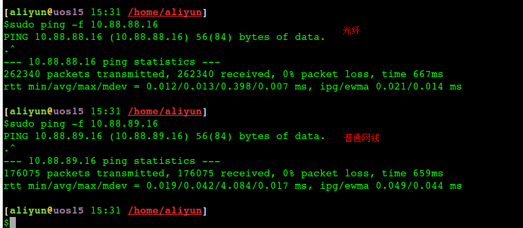
[aliyun@uos15 11:00 /home/aliyun] 以下88都是光口、89都是电口。
$ping -c 10 10.88.88.16 //光纤
PING 10.88.88.16 (10.88.88.16) 56(84) bytes of data.
64 bytes from 10.88.88.16: icmp_seq=1 ttl=64 time=0.058 ms
64 bytes from 10.88.88.16: icmp_seq=2 ttl=64 time=0.049 ms
64 bytes from 10.88.88.16: icmp_seq=3 ttl=64 time=0.053 ms
64 bytes from 10.88.88.16: icmp_seq=4 ttl=64 time=0.040 ms
64 bytes from 10.88.88.16: icmp_seq=5 ttl=64 time=0.053 ms
64 bytes from 10.88.88.16: icmp_seq=6 ttl=64 time=0.043 ms
64 bytes from 10.88.88.16: icmp_seq=7 ttl=64 time=0.038 ms
64 bytes from 10.88.88.16: icmp_seq=8 ttl=64 time=0.050 ms
64 bytes from 10.88.88.16: icmp_seq=9 ttl=64 time=0.043 ms
64 bytes from 10.88.88.16: icmp_seq=10 ttl=64 time=0.064 ms
--- 10.88.88.16 ping statistics ---
10 packets transmitted, 10 received, 0% packet loss, time 159ms
rtt min/avg/max/mdev = 0.038/0.049/0.064/0.008 ms
[aliyun@uos15 11:01 /home/aliyun]
$ping -c 10 10.88.89.16 //电口
PING 10.88.89.16 (10.88.89.16) 56(84) bytes of data.
64 bytes from 10.88.89.16: icmp_seq=1 ttl=64 time=0.087 ms
64 bytes from 10.88.89.16: icmp_seq=2 ttl=64 time=0.053 ms
64 bytes from 10.88.89.16: icmp_seq=3 ttl=64 time=0.095 ms
64 bytes from 10.88.89.16: icmp_seq=4 ttl=64 time=0.391 ms
64 bytes from 10.88.89.16: icmp_seq=5 ttl=64 time=0.051 ms
64 bytes from 10.88.89.16: icmp_seq=6 ttl=64 time=0.343 ms
64 bytes from 10.88.89.16: icmp_seq=7 ttl=64 time=0.045 ms
64 bytes from 10.88.89.16: icmp_seq=8 ttl=64 time=0.341 ms
64 bytes from 10.88.89.16: icmp_seq=9 ttl=64 time=0.054 ms
64 bytes from 10.88.89.16: icmp_seq=10 ttl=64 time=0.066 ms
--- 10.88.89.16 ping statistics ---
10 packets transmitted, 10 received, 0% packet loss, time 149ms
rtt min/avg/max/mdev = 0.045/0.152/0.391/0.136 ms
[aliyun@uos15 11:02 /u01]
$scp uos.tar aliyun@10.88.89.16:/tmp/
uos.tar 100% 3743MB 111.8MB/s 00:33
[aliyun@uos15 11:03 /u01]
$scp uos.tar aliyun@10.88.88.16:/tmp/
uos.tar 100% 3743MB 178.7MB/s 00:20
[aliyun@uos15 11:07 /u01]
$sudo ping -f 10.88.89.16
PING 10.88.89.16 (10.88.89.16) 56(84) bytes of data.
--- 10.88.89.16 ping statistics ---
284504 packets transmitted, 284504 received, 0% packet loss, time 702ms
rtt min/avg/max/mdev = 0.019/0.040/1.014/0.013 ms, ipg/ewma 0.048/0.042 ms
[aliyun@uos15 11:07 /u01]
$sudo ping -f 10.88.88.16
PING 10.88.88.16 (10.88.88.16) 56(84) bytes of data.
--- 10.88.88.16 ping statistics ---
299748 packets transmitted, 299748 received, 0% packet loss, time 242ms
rtt min/avg/max/mdev = 0.012/0.016/0.406/0.006 ms, pipe 2, ipg/ewma 0.034/0.014 ms

多网卡bonding

1
2
3
4
5
6
7
8
9
10
11
12
13
14
15
16
17
18
19
20
21
22
23
24
25
26
27
28
29
30
31
#cat ifcfg-bond0
DEVICE=bond0
TYPE=Bond
ONBOOT=yes
BOOTPROTO=static
IPADDR=10.176.7.11
NETMASK=255.255.255.0
#cat /etc/sysconfig/network-scripts/ifcfg-eth0
DEVICE=eth0
TYPE=Ethernet
ONBOOT=yes
BOOTPROTO=none
MASTER=bond0
SLAVE=yes
#cat /etc/sysconfig/network-scripts/ifcfg-eth1
DEVICE=eth1
TYPE=Ethernet
ONBOOT=yes
BOOTPROTO=none
MASTER=bond0
SLAVE=yes
#cat /proc/net/bonding/bond0
----加载内核bonding模块, mode=0 是RR负载均衡模式
#cat /etc/modprobe.d/bonding.conf
# modprobe bonding
alias bond0 bonding
options bond0 mode=0 miimon=100 //这一行也可以放到bond0配置文件中,比如:BONDING_OPTS="miimon=100 mode=4 xmit_hash_policy=layer3+4" 用iperf 多连接测试bonding后的带宽发现,发送端能用上两张网卡,但是接收队列只能使用一张物理网卡

网卡绑定mode共有七种(0~6) bond0、bond1、bond2、bond3、bond4、bond5、bond6

常用的有三种

  • mode=0:平衡负载模式 (balance-rr),有自动备援,两块物理网卡和bond网卡使用同一个mac地址,但需要”Switch”支援及设定。

  • mode=1:自动备援模式 (balance-backup),其中一条线若断线,其他线路将会自动备援。

  • mode=6:平衡负载模式(balance-alb),有自动备援,不必”Switch”支援及设定,两块网卡是使用不同的MAC地址

  • Mode 4 (802.3ad): This mode creates aggregation groups that share the same speed and duplex settings, and it requires a switch that supports an IEEE 802.3ad dynamic link. Mode 4 uses all interfaces in the active aggregation group. For example, you can aggregate three 1 GB per second (GBPS) ports into a 3 GBPS trunk port. This is equivalent to having one interface with 3 GBPS speed. It provides fault tolerance and load balancing.

需要说明的是如果想做成mode 0的负载均衡,仅仅设置这里options bond0 miimon=100 mode=0是不够的,与网卡相连的交换机必须做特殊配置(这两个端口应该采取聚合方式),因为做bonding的这两块网卡是使用同一个MAC地址.从原理分析一下(bond运行在mode 0下):

mode 0下bond所绑定的网卡的IP都被修改成相同的mac地址,如果这些网卡都被接在同一个交换机,那么交换机的arp表里这个mac地址对应的端口就有多 个,那么交换机接受到发往这个mac地址的包应该往哪个端口转发呢?正常情况下mac地址是全球唯一的,一个mac地址对应多个端口肯定使交换机迷惑了。所以 mode0下的bond如果连接到交换机,交换机这几个端口应该采取聚合方式(cisco称为 ethernetchannel,foundry称为portgroup),因为交换机做了聚合后,聚合下的几个端口也被捆绑成一个mac地址.我们的解决办法是,两个网卡接入不同的交换机即可。

mode6模式下无需配置交换机,因为做bonding的这两块网卡是使用不同的MAC地址。

mod=5,即:(balance-tlb) Adaptive transmit load balancing(适配器传输负载均衡)

特点:不需要任何特别的switch(交换机)支持的通道bonding。在每个slave上根据当前的负载(根据速度计算)分配外出流量。如果正在接受数据的slave出故障了,另一个slave接管失败的slave的MAC地址。

该模式的必要条件:ethtool支持获取每个slave的速率.

案例,两块万兆bonding后带宽翻倍

1
2
3
4
5
6
7
8
9
10
11
12
13
14
15
16
17
18
19
20
21
22
23
24
25
26
27
28
29
30
31
32
33
34
35
36
37
38
39
40
41
42
43
44
45
46
47
48
49
50
51
52
53
54
55
56
57
58
#ethtool bond0
Settings for bond0:
Supported ports: [ ]
Supported link modes: Not reported
Supported pause frame use: No
Supports auto-negotiation: No
Advertised link modes: Not reported
Advertised pause frame use: No
Advertised auto-negotiation: No
Speed: 20000Mb/s
Duplex: Full
Port: Other
PHYAD: 0
Transceiver: internal
Auto-negotiation: off
Link detected: yes
[root@phy 16:55 /root]
#cat /etc/sysconfig/network-scripts/ifcfg-bond0
DEVICE=bond0
BOOTPROTO=static
TYPE="ethernet"
IPADDR=100.1.1.2
NETMASK=255.255.255.192
ONBOOT=yes
USERCTL=no
PEERDNS=no
BONDING_OPTS="miimon=100 mode=4 xmit_hash_policy=layer3+4"
#cat /etc/modprobe.d/bonding.conf
alias netdev-bond0 bonding
#lsmod |grep bond
bonding 137339 0
#cat ifcfg-bond0
DEVICE=bond0
BOOTPROTO=static
TYPE="ethernet"
IPADDR=100.81.131.221
NETMASK=255.255.255.192
ONBOOT=yes
USERCTL=no
PEERDNS=no
BONDING_OPTS="miimon=100 mode=4 xmit_hash_policy=layer3+4"
#cat ifcfg-eth1
DEVICE=eth1
TYPE="Ethernet"
HWADDR=7C:D3:0A:E0:F7:81
BOOTPROTO=none
ONBOOT=yes
MASTER=bond0
SLAVE=yes
PEERDNS=no
RX_MAX=`ethtool -g "$DEVICE" | grep 'Pre-set' -A1 | awk '/RX/{print $2}'`
RX_CURRENT=`ethtool -g "$DEVICE" | grep "Current" -A1 | awk '/RX/{print $2}'`
[[ "$RX_CURRENT" -lt "$RX_MAX" ]] && ethtool -G "$DEVICE" rx "$RX_MAX"

网络中断和绑核

网络包的描述符的内存(RingBuffer)跟着设备走(设备在哪个Die/Node上,就近分配内存), 数据缓冲区(Data Buffer–存放网络包)内存跟着队列(中断)走, 如果队列绑定到DIE0, 而设备在die1上,这样在做DMA通信时, 会产生跨die的交织访问

不管设备插在哪一个die上, 只要描述符申请的内存和数据缓冲区的内存都在同一个die上(需要修改驱动源代码–非常规),就能避免跨die内存交织, 性能能保持一致。

irqbalance服务不会将中断进行跨node迁移,只会在同一numa node中进行优化。

ethtool

1
2
3
4
5
6
7
8
9
10
11
12
13
14
15
16
17
18
19
20
#ethtool -i p1p1 //查询网卡bus-info
driver: mlx5_core
version: 5.0-0
firmware-version: 14.27.1016 (MT_2420110004)
expansion-rom-version:
bus-info: 0000:21:00.0
supports-statistics: yes
supports-test: yes
supports-eeprom-access: no
supports-register-dump: no
supports-priv-flags: yes
//根据bus-info找到中断id
#cat /proc/interrupts | grep 0000:21:00.0 | awk -F: '{print $1}' | wc -l
//修改网卡队列数
sudo ethtool -L eth0 combined 2 (不能超过网卡最大队列数)
然后检查是否生效了(不需要重启应用和机器,实时生效):
sudo ethtool -l eth0

根据网卡bus-info可以找到对应的irq id

手工绑核脚本:

1
2
3
4
5
6
7
8
9
10
11
#!/bin/bash
#irq_list=(`cat /proc/interrupts | grep enp131s0 | awk -F: '{print $1}'`)
intf=$1
irq_list=(cat /proc/interrupts | grep `ethtool -i $intf |grep bus-info | awk '{ print $2 }'` | awk -F: '{print $1}')
cpunum=48 # 修改为所在node的第一个Core
for irq in ${irq_list[@]}
do
echo $cpunum > /proc/irq/$irq/smp_affinity_list
echo `cat /proc/irq/$irq/smp_affinity_list`
(( cpunum+=1 ))
done

检查绑定结果: sh irqCheck.sh enp131s0

1
2
3
4
5
6
7
8
9
10
11
12
13
14
15
16
17
18
19
# 网卡名
intf=$1
irqID=`ethtool -i $intf |grep bus-info | awk '{ print $2 }'`
log=irqSet-`date "+%Y%m%d-%H%M%S"`.log
# 可用的CPU数
cpuNum=$(cat /proc/cpuinfo |grep processor -c)
# RX TX中断列表
irqListRx=$(cat /proc/interrupts | grep ${irqID} | awk -F':' '{print $1}')
irqListTx=$(cat /proc/interrupts | grep ${irqID} | awk -F':' '{print $1}')
# 绑定接收中断rx irq
for irqRX in ${irqListRx[@]}
do
cat /proc/irq/${irqRX}/smp_affinity_list
done
# 绑定发送中断tx irq
for irqTX in ${irqListTx[@]}
do
cat /proc/irq/${irqTX}/smp_affinity_list
done

中断联合(Coalescing)

中断联合可供我们推迟向内核通告新事件的操作,将多个事件汇总在一个中断中通知内核。该功能的当前设置可通过ethtool -c查看:

1
2
3
4
5
$ ethtool -c eth0
Coalesce parameters for eth0:
...
rx-usecs: 50
tx-usecs: 50

此处可以设置固定上限,对每内核每秒处理中断数量的最大值进行硬性限制,或针对特定硬件根据吞吐率自动调整中断速率

启用联合(使用-C)会增大延迟并可能导致丢包,因此对延迟敏感的工作可能需要避免这样做。另外,彻底禁用该功能可能导致中断受到节流限制,进而影响性能。

多次在nginx场景下测试未发现这个值对TPS有什么明显的改善

How to achieve low latency with 10Gbps Ethernet 中有提到 Linux 3.11 added support for the SO_BUSY_POLL socket option. 也有类似的作用

irqbalance

irqbalance 是一个命令行工具,在处理器中分配硬件中断以提高系统性能。默认设置下在后台程序运行,但只可通过 --oneshot 选项运行一次。

以下参数可用于提高性能。

  • –powerthresh

    CPU 进入节能模式之前,设定可空闲的 CPU 数量。如果有大于阀值数量的 CPU 是大于一个标准的偏差,该差值低于平均软中断工作负载,以及没有 CPU 是大于一个标准偏差,且该偏差高出平均,并有多于一个的 irq 分配给它们,一个 CPU 将处于节能模式。在节能模式中,CPU 不是 irqbalance 的一部分,所以它在有必要时才会被唤醒。

  • –hintpolicy

    决定如何解决 irq 内核关联提示。有效值为 exact(总是应用 irq 关联提示)、subset (irq 是平衡的,但分配的对象是关联提示的子集)、或者 ignore(irq 完全被忽略)。

  • –policyscript

    通过设备路径、当作参数的irq号码以及 irqbalance 预期的零退出代码,定义脚本位置以执行每个中断请求。定义的脚本能指定零或多键值对来指导管理传递的 irq 中 irqbalance。下列是为效键值对:ban有效值为 true(从平衡中排除传递的 irq)或 false(该 irq 表现平衡)。balance_level允许用户重写传递的 irq 平衡度。默认设置下,平衡度基于拥有 irq 设备的 PCI 设备种类。有效值为 nonepackagecache、或 core。numa_node允许用户重写视作为本地传送 irq 的 NUMA 节点。如果本地节点的信息没有限定于 ACPI ,则设备被视作与所有节点距离相等。有效值为识别特定 NUMA 节点的整数(从0开始)和 -1,规定 irq 应被视作与所有节点距离相等。

  • –banirq

    将带有指定中断请求号码的中断添加至禁止中断的列表。

也可以使用 IRQBALANCE_BANNED_CPUS 环境变量来指定被 irqbalance 忽略的 CPU 掩码。

1
2
3
4
5
//默认irqbalance绑定一个numa, -1指定多个numa
echo -1 >/sys/bus/pci/devices/`ethtool -i p1p1 |grep bus-info | awk '{ print $2 }'`/numa_node ;
// 目录 /sys/class/net/p1p1/ link到了 /sys/bus/pci/devices/`ethtool -i p1p1 |grep bus-info | awk '{ print $2 }'`
执行 irqbalance --debug 进行调试

irqbalance指定core

1
2
3
4
5
6
7
8
9
10
11
12
13
cat /etc/sysconfig/irqbalance
# IRQBALANCE_BANNED_CPUS
# 64 bit bitmask which allows you to indicate which cpu's should
# be skipped when reblancing irqs. Cpu numbers which have their
# corresponding bits set to one in this mask will not have any
# irq's assigned to them on rebalance
#绑定软中断到8-15core, 每位表示4core
#IRQBALANCE_BANNED_CPUS=ffffffff,ffff00ff
#绑定软中断到8-15core和第65core
IRQBALANCE_BANNED_CPUS=ffffffff,fffffdff,ffffffff,ffff00ff
#96core 鲲鹏920下绑前16core
IRQBALANCE_BANNED_CPUS=ffffffff,ffffffff,ffff0000

irqbalance的流程

初始化的过程只是建立链表的过程,暂不描述,只考虑正常运行状态时的流程
-处理间隔是10s
-清除所有中断的负载值
-/proc/interrupts读取中断,并记录中断数
-/proc/stat读取每个cpu的负载,并依次计算每个层次每个节点的负载以及每个中断的负载
-通过平衡算法找出需要重新分配的中断
-把需要重新分配的中断加入到新的节点中
-配置smp_affinity使处理生效

irqbalance服务不会将中断进行跨node迁移,只会在同一numa node中进行优化。

网卡软中断以及内存远近的测试结论

一般网卡中断会占用一些CPU,如果把网卡中断挪到其它node的core上,在鲲鹏920上测试(网卡插在node0上),业务跑在node3,网卡中断分别在node0和node3,QPS分别是:179000 VS 175000

如果将业务跑在node0上,网卡中断分别在node0和node1上得到的QPS分别是:204000 VS 212000

以上测试的时候业务进程分配的内存全限制在node0上

1
2
3
4
5
6
7
8
9
10
#/root/numa-maps-summary.pl </proc/123853/numa_maps
N0 : 5085548 ( 19.40 GB)
N1 : 4479 ( 0.02 GB)
N2 : 1 ( 0.00 GB)
active : 0 ( 0.00 GB)
anon : 5085455 ( 19.40 GB)
dirty : 5085455 ( 19.40 GB)
kernelpagesize_kB: 2176 ( 0.01 GB)
mapmax : 348 ( 0.00 GB)
mapped : 4626 ( 0.02 GB)

从以上测试数据可以看到在这个内存分布场景下,如果就近访问内存性能有20%以上的提升

一般默认申请的data buffer也都在设备所在的numa节点上, 如果将队列的中断绑定到其他cpu上, 那么队列申请的data buffer的节点也会跟着中断迁移。

阿里云绑核脚本

通常情况下,Linux的网卡中断是由一个CPU核心来处理的,当承担高流量的场景下,会出现一些诡异的情况(网卡尚未达到瓶颈,但是却出现丢包的情况)

这种时候,我们最好看下网卡中断是不是缺少调优。

优化3要点:网卡多队列+irq affinity亲缘性设置+关闭irqbalance (systemctl stop irqbalance)

目前阿里云官方提供的centos和ubuntu镜像里面,已经自带了优化脚本,内容如下:

centos7的脚本路径在 /usr/sbin/ecs_mq_rps_rfs 具体内容如下:

1
2
3
4
5
6
7
8
9
10
11
12
13
14
15
16
17
18
19
20
21
22
23
24
25
26
27
28
29
30
31
32
33
34
35
36
37
38
39
40
41
42
43
44
45
46
47
48
49
50
51
52
53
54
55
56
57
58
59
60
61
62
63
64
65
66
67
68
69
70
71
72
73
74
75
76
77
78
79
80
81
82
83
84
85
86
87
88
89
90
91
92
93
94
95
96
97
98
99
100
101
102
103
104
105
106
107
108
109
110
111
112
113
114
115
116
117
118
119
120
121
122
123
124
125
#!/bin/bash
# This is the default setting of networking multiqueue and irq affinity
# 1. enable multiqueue if available
# 2. irq affinity optimization
# 3. stop irqbalance service
# set and check multiqueue
function set_check_multiqueue()
{
eth=$1
log_file=$2
queue_num=$(ethtool -l $eth | grep -ia5 'pre-set' | grep -i combined | awk {'print $2'})
if [ $queue_num -gt 1 ]; then
# set multiqueue
ethtool -L $eth combined $queue_num
# check multiqueue setting
cur_q_num=$(ethtool -l $eth | grep -iA5 current | grep -i combined | awk {'print $2'})
if [ "X$queue_num" != "X$cur_q_num" ]; then
echo "Failed to set $eth queue size to $queue_num" >> $log_file
echo "after setting, pre-set queue num: $queue_num , current: $cur_q_num" >> $log_file
return 1
else
echo "OK. set $eth queue size to $queue_num" >> $log_file
fi
else
echo "only support $queue_num queue; no need to enable multiqueue on $eth" >> $log_file
fi
}
#set irq affinity
function set_irq_smpaffinity()
{
log_file=$1
node_dir=/sys/devices/system/node
for i in $(ls -d $node_dir/node*); do
i=${i/*node/}
done
echo "max node :$i" >> $log_file
node_cpumax=$(cat /sys/devices/system/node/node${i}/cpulist |awk -F- '{print $NF}')
irqs=($(cat /proc/interrupts |grep virtio |grep put | awk -F: '{print $1}'))
core=0
for irq in ${irqs[@]};do
VEC=$core
if [ $VEC -ge 32 ];then
let "IDX = $VEC / 32"
MASK_FILL=""
MASK_ZERO="00000000"
for ((i=1; i<=$IDX;i++))
do
MASK_FILL="${MASK_FILL},${MASK_ZERO}"
done
let "VEC -= 32 * $IDX"
MASK_TMP=$((1<<$VEC))
MASK=$(printf "%X%s" $MASK_TMP $MASK_FILL)
else
MASK_TMP=$((1<<$VEC))
MASK=$(printf "%X" $MASK_TMP)
fi
echo $MASK > /proc/irq/$irq/smp_affinity
echo "mask:$MASK, irq:$irq" >> $log_file
core=$(((core+1)%(node_cpumax+1)))
done
}
# stop irqbalance service
function stop_irqblance()
{
log_file=$1
ret=0
if [ "X" != "X$(ps -ef | grep irqbalance | grep -v grep)" ]; then
if which systemctl;then
systemctl stop irqbalance
else
service irqbalance stop
fi
if [ $? -ne 0 ]; then
echo "Failed to stop irqbalance" >> $log_file
ret=1
fi
else
echo "OK. irqbalance stoped." >> $log_file
fi
return $ret
}
# main logic
function main()
{
ecs_network_log=/var/log/ecs_network_optimization.log
ret_value=0
echo "running $0" > $ecs_network_log
echo "======== ECS network setting starts $(date +'%Y-%m-%d %H:%M:%S') ========" >> $ecs_network_log
# we assume your NIC interface(s) is/are like eth*
eth_dirs=$(ls -d /sys/class/net/eth*)
if [ "X$eth_dirs" = "X" ]; then
echo "ERROR! can not find any ethX in /sys/class/net/ dir." >> $ecs_network_log
ret_value=1
fi
for i in $eth_dirs
do
cur_eth=$(basename $i)
echo "optimize network performance: current device $cur_eth" >> $ecs_network_log
# only optimize virtio_net device
driver=$(basename $(readlink $i/device/driver))
if ! echo $driver | grep -q virtio; then
echo "ignore device $cur_eth with driver $driver" >> $ecs_network_log
continue
fi
echo "set and check multiqueue on $cur_eth" >> $ecs_network_log
set_check_multiqueue $cur_eth $ecs_network_log
if [ $? -ne 0 ]; then
echo "Failed to set multiqueue on $cur_eth" >> $ecs_network_log
ret_value=1
fi
done
stop_irqblance $ecs_network_log
set_irq_smpaffinity $ecs_network_log
echo "======== ECS network setting END $(date +'%Y-%m-%d %H:%M:%S') ========" >> $ecs_network_log
return $ret_value
}
# program starts here
main
exit $?

查询的rps绑定情况的脚本 get_rps.sh

1
2
3
4
5
6
#!/bin/bash
# 获取当前rps情况
for i in $(ls /sys/class/net/eth0/queues/rx-*/rps_cpus); do
echo $i
cat $i
done
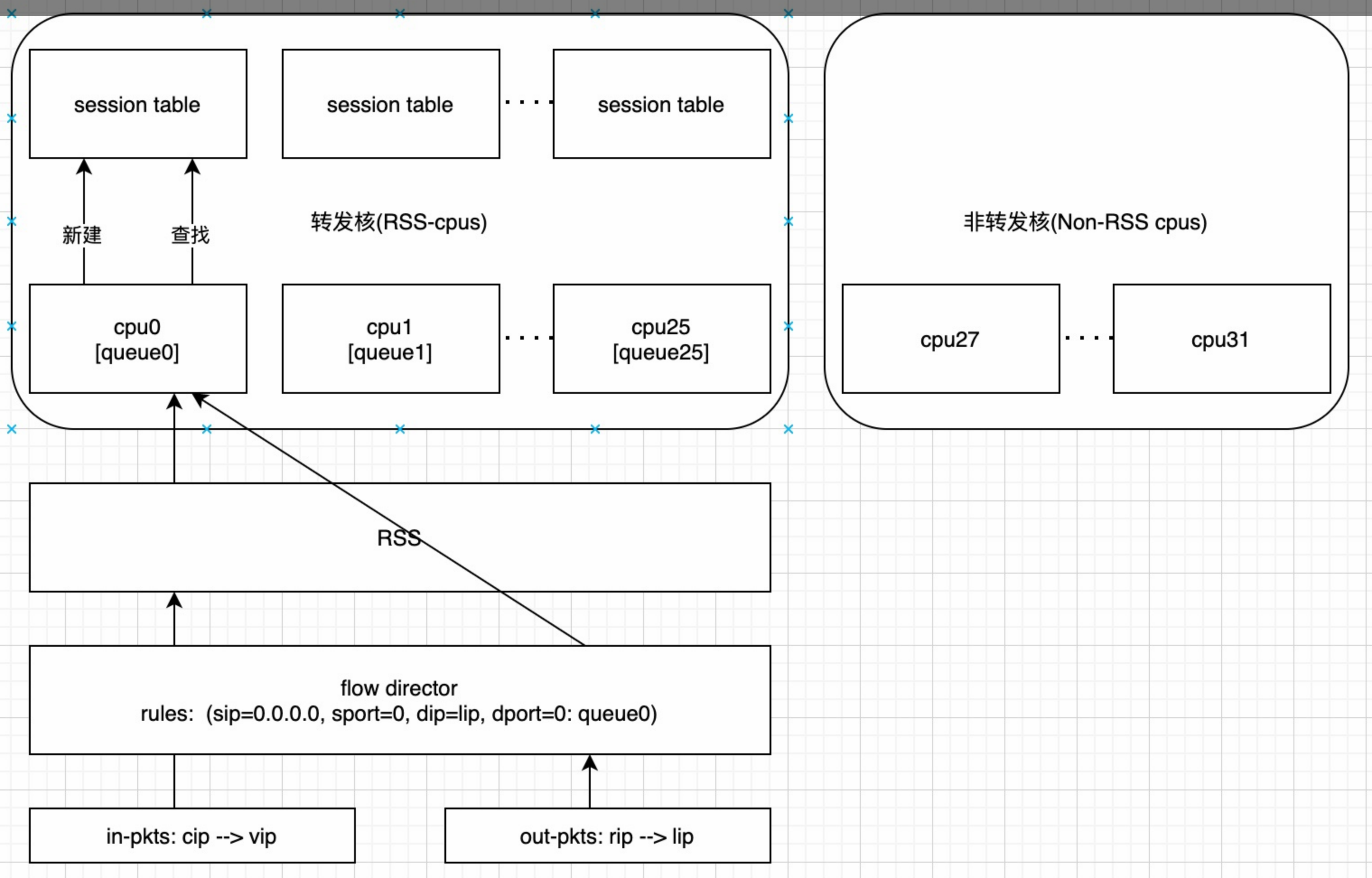
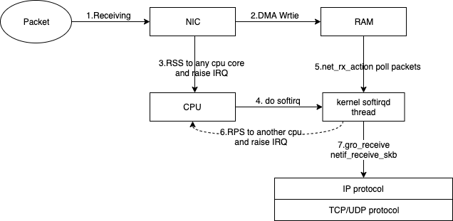
RSS 和 RPS

  • RSS:即receive side steering,利用网卡的多队列特性,将每个核分别跟网卡的一个首发队列绑定,以达到网卡硬中断和软中断均衡的负载在各个CPU上。他要求网卡必须要支持多队列特性。
  • RPS:receive packet steering,他把收到的packet依据一定的hash规则给hash到不同的CPU上去,以达到各个CPU负载均衡的目的。他只是把软中断做负载均衡,不去改变硬中断。因而对网卡没有任何要求。
  • RFS:receive flow steering,RFS需要依赖于RPS,他跟RPS不同的是不再简单的依据packet来做hash,而是根据flow的特性,即application在哪个核上来运行去做hash,从而使得有更好的数据局部性。

RSS

image-20221125190002856

设置 RPS,首先内核要开启CONFIG_RPS编译选项,然后设置需要将中断分配到哪些CPU:

1
2
#cat /sys/class/net/eth3/queues/rx-[0-7]/rps_cpus
#cat /sys/class/net/eth3/queues/tx-[0-7]/xps_cpus

我们可以看到很多案例,使用这些特性后提醒了网络包的处理能力,从而提升QPS,降低RT。

Image

如上图所示,数据包在进入内核IP/TCP协议栈之前,经历了这些步骤:

  1. 网口(NIC)收到packets
  2. 网口通过DMA(Direct memeory access)将数据写入到内存(RAM)中。
  3. 网口通过RSS(网卡多队列)将收到的数据包分发给某个rx队列,并触发该队列所绑定核上的CPU中断。
  4. 收到中断的核,调用该核所在的内核软中断线程(softirqd)进行后续处理。
  5. softirqd负责将数据包从RAM中取到内核中。
  6. 如果开启了RPS,RPS会选择一个目标cpu核来处理该包,如果目标核非当前正在运行的核,则会触发目标核的IPI(处理器之间中断),并将数据包放在目标核的backlog队列中。
  7. 软中断线程将数据包(数据包可能来源于第5步、或第6步),通过gro(generic receive offload,如果开启的话)等处理后,送往IP协议栈,及之后的TCP/UDP等协议栈。

查看网卡和numa的关系

1
2
3
4
5
6
7
8
9
10
11
12
13
14
#yum install lshw -y
#lshw -C network -short
H/W path Device Class Description
=============================================================
/0/100/0/9/0 eth0 network MT27710 Family [ConnectX-4 Lx]
/0/100/0/9/0.1 eth1 network MT27710 Family [ConnectX-4 Lx]
/1 e41358fae4ee_h network Ethernet interface
/2 86b0637ef1e1_h network Ethernet interface
/3 a6706e785f53_h network Ethernet interface
/4 d351290e50a0_h network Ethernet interface
/5 1a9e5df98dd1_h network Ethernet interface
/6 766ec0dab599_h network Ethernet interface
/7 bond0.11 network Ethernet interface
/8 ea004888c217_h network Ethernet interface

以及:

1
2
3
lscpu | grep -i numa
numactl --hardware
cat /proc/interrupts | egrep -i "CPU|rx"

Check if the network interfaces are tied to Numa (if -1 means not tied, if 0, then to numa0):

1
cat /sys/class/net/eth0/device/numa_node

You can see which NAMA the network card belongs to, for example, using lstopo:

1
2
3
4
5
6
7
8
9
10
11
12
13
14
15
16
17
18
19
20
21
22
23
24
25
26
27
28
29
30
31
32
33
34
35
36
37
38
39
40
41
42
43
44
45
46
47
48
49
50
51
52
53
54
55
56
57
58
59
60
61
62
63
64
65
66
67
68
69
70
71
72
73
74
75
76
77
78
79
80
81
82
83
84
85
86
87
88
89
90
91
92
93
94
95
96
97
98
99
100
101
102
103
104
105
106
107
108
109
110
111
112
113
114
115
116
117
118
119
120
121
122
123
124
125
126
127
128
129
130
131
132
133
134
135
136
137
138
139
140
141
142
143
144
145
146
147
148
149
150
151
152
153
154
155
156
157
158
159
160
161
162
163
164
165
166
167
168
169
170
171
172
173
174
175
176
177
178
179
180
181
182
183
184
185
186
187
188
189
190
191
192
193
194
yum install hwloc -y
lstopo
lstopo --logical
lstopo --logical --output-format png > lstopo.png
--
[root@hygon3 10:58 /root] //hygon 7280 CPU
#lstopo --logical
Machine (503GB total) //总内存大小
NUMANode L#0 (P#0 252GB) //socket0、numa0 的内存大小
Package L#0
L3 L#0 (8192KB) //L3 cache,对应4个物理core,8个HT
L2 L#0 (512KB) + L1d L#0 (32KB) + L1i L#0 (64KB) + Core L#0 // L1/L2
PU L#0 (P#0)
PU L#1 (P#64)
L2 L#1 (512KB) + L1d L#1 (32KB) + L1i L#1 (64KB) + Core L#1
PU L#2 (P#1)
PU L#3 (P#65)
L2 L#2 (512KB) + L1d L#2 (32KB) + L1i L#2 (64KB) + Core L#2
PU L#4 (P#2)
PU L#5 (P#66)
L2 L#3 (512KB) + L1d L#3 (32KB) + L1i L#3 (64KB) + Core L#3
PU L#6 (P#3)
PU L#7 (P#67)
L3 L#1 (8192KB)
L3 L#2 (8192KB)
L3 L#3 (8192KB)
L3 L#4 (8192KB)
L3 L#5 (8192KB)
L3 L#6 (8192KB)
L3 L#7 (8192KB)
HostBridge L#0
PCIBridge
PCIBridge
PCI 1a03:2000
GPU L#0 "controlD64"
GPU L#1 "card0"
PCIBridge
PCI 1d94:7901
Block(Disk) L#2 "sdm" //ssd系统盘,接在Node0上,绑核有优势
HostBridge L#4
PCIBridge
PCI 1000:0097
PCIBridge
PCI 1c5f:000d
PCIBridge
PCI 1c5f:000d
HostBridge L#8
PCIBridge
PCI 15b3:1015
Net L#3 "p1p1" //万兆网卡接在Node0上
PCI 15b3:1015
Net L#4 "p1p2"
HostBridge L#10
PCIBridge
PCI 8086:1521
Net L#5 "em1" //千兆网卡接在Node0上
PCI 8086:1521
Net L#6 "em2"
NUMANode L#1 (P#1 251GB) //另外一个socket
Package L#1
L3 L#8 (8192KB)
L2 L#32 (512KB) + L1d L#32 (32KB) + L1i L#32 (64KB) + Core L#32
----------- FT2500 两路共128core
#lstopo-no-graphics --logical
Machine (503GB total)
Package L#0 + L3 L#0 (64MB)
NUMANode L#0 (P#0 31GB)
L2 L#0 (2048KB) //4个物理core共享2M
L1d L#0 (32KB) + L1i L#0 (32KB) + Core L#0 + PU L#0 (P#0)
L1d L#1 (32KB) + L1i L#1 (32KB) + Core L#1 + PU L#1 (P#1)
L1d L#2 (32KB) + L1i L#2 (32KB) + Core L#2 + PU L#2 (P#2)
L1d L#3 (32KB) + L1i L#3 (32KB) + Core L#3 + PU L#3 (P#3)
L2 L#1 (2048KB)
L1d L#4 (32KB) + L1i L#4 (32KB) + Core L#4 + PU L#4 (P#4)
L1d L#5 (32KB) + L1i L#5 (32KB) + Core L#5 + PU L#5 (P#5)
L1d L#6 (32KB) + L1i L#6 (32KB) + Core L#6 + PU L#6 (P#6)
L1d L#7 (32KB) + L1i L#7 (32KB) + Core L#7 + PU L#7 (P#7)
HostBridge L#0
PCIBridge
PCIBridge
PCIBridge
PCI 1000:00ac
Block(Disk) L#0 "sdh"
Block(Disk) L#1 "sdf" // 磁盘挂在Node0上
PCIBridge
PCI 8086:1521
Net L#13 "eth0"
PCI 8086:1521
Net L#14 "eth1" //网卡挂在node0上
PCIBridge
PCIBridge
PCI 1a03:2000
GPU L#15 "controlD64"
GPU L#16 "card0"
NUMANode L#1 (P#1 31GB)
NUMANode L#2 (P#2 31GB)
NUMANode L#3 (P#3 31GB)
NUMANode L#4 (P#4 31GB)
NUMANode L#5 (P#5 31GB)
NUMANode L#6 (P#6 31GB)
NUMANode L#7 (P#7 31GB)
L2 L#14 (2048KB)
L1d L#56 (32KB) + L1i L#56 (32KB) + Core L#56 + PU L#56 (P#56)
L1d L#57 (32KB) + L1i L#57 (32KB) + Core L#57 + PU L#57 (P#57)
L1d L#58 (32KB) + L1i L#58 (32KB) + Core L#58 + PU L#58 (P#58)
L1d L#59 (32KB) + L1i L#59 (32KB) + Core L#59 + PU L#59 (P#59)
L2 L#15 (2048KB)
L1d L#60 (32KB) + L1i L#60 (32KB) + Core L#60 + PU L#60 (P#60)
L1d L#61 (32KB) + L1i L#61 (32KB) + Core L#61 + PU L#61 (P#61)
L1d L#62 (32KB) + L1i L#62 (32KB) + Core L#62 + PU L#62 (P#62)
L1d L#63 (32KB) + L1i L#63 (32KB) + Core L#63 + PU L#63 (P#63)
Package L#1 + L3 L#1 (64MB) //socket2
NUMANode L#8 (P#8 31GB)
L2 L#16 (2048KB)
L1d L#64 (32KB) + L1i L#64 (32KB) + Core L#64 + PU L#64 (P#64)
L1d L#65 (32KB) + L1i L#65 (32KB) + Core L#65 + PU L#65 (P#65)
L1d L#66 (32KB) + L1i L#66 (32KB) + Core L#66 + PU L#66 (P#66)
L1d L#67 (32KB) + L1i L#67 (32KB) + Core L#67 + PU L#67 (P#67)
L2 L#17 (2048KB)
L1d L#68 (32KB) + L1i L#68 (32KB) + Core L#68 + PU L#68 (P#68)
L1d L#69 (32KB) + L1i L#69 (32KB) + Core L#69 + PU L#69 (P#69)
L1d L#70 (32KB) + L1i L#70 (32KB) + Core L#70 + PU L#70 (P#70)
L1d L#71 (32KB) + L1i L#71 (32KB) + Core L#71 + PU L#71 (P#71)
HostBridge L#7
PCIBridge
PCIBridge
PCIBridge
PCI 15b3:1015
Net L#17 "eth2" //node8 上的网卡,eth2、eth3做了bonding
PCI 15b3:1015
Net L#18 "eth3"
PCIBridge
PCI 144d:a808
PCIBridge
PCI 144d:a808
---鲲鹏920 每路48core 2路共4node,网卡插在node0,磁盘插在node2
#lstopo-no-graphics
Machine (755GB total)
Package L#0
NUMANode L#0 (P#0 188GB)
L3 L#0 (24MB)
L2 L#0 (512KB) + L1d L#0 (64KB) + L1i L#0 (64KB) + Core L#0 + PU L#0 (P#0)
L2 L#1 (512KB) + L1d L#1 (64KB) + L1i L#1 (64KB) + Core L#1 + PU L#1 (P#1)
L2 L#22 (512KB) + L1d L#22 (64KB) + L1i L#22 (64KB) + Core L#22 + PU L#22 (P#22)
L2 L#23 (512KB) + L1d L#23 (64KB) + L1i L#23 (64KB) + Core L#23 + PU L#23 (P#23)
HostBridge L#0
PCIBridge
PCI 15b3:1017
Net L#0 "enp2s0f0"
PCI 15b3:1017
Net L#1 "eth1"
PCIBridge
PCI 19e5:1711
GPU L#2 "controlD64"
GPU L#3 "card0"
HostBridge L#3
2 x { PCI 19e5:a230 }
PCI 19e5:a235
Block(Disk) L#4 "sda"
HostBridge L#4
PCIBridge
PCI 19e5:a222
Net L#5 "enp125s0f0"
PCI 19e5:a221
Net L#6 "enp125s0f1"
PCI 19e5:a222
Net L#7 "enp125s0f2"
PCI 19e5:a221
Net L#8 "enp125s0f3"
NUMANode L#1 (P#1 189GB) + L3 L#1 (24MB)
L2 L#24 (512KB) + L1d L#24 (64KB) + L1i L#24 (64KB) + Core L#24 + PU L#24 (P#24)
Package L#1
NUMANode L#2 (P#2 189GB)
L3 L#2 (24MB)
L2 L#48 (512KB) + L1d L#48 (64KB) + L1i L#48 (64KB) + Core L#48 + PU L#48 (P#48)
HostBridge L#6
PCIBridge
PCI 19e5:3714
PCIBridge
PCI 19e5:3714
PCIBridge
PCI 19e5:3714
PCIBridge
PCI 19e5:3714
HostBridge L#11
PCI 19e5:a230
PCI 19e5:a235
PCI 19e5:a230
NUMANode L#3 (P#3 189GB) + L3 L#3 (24MB)
L2 L#72 (512KB) + L1d L#72 (64KB) + L1i L#72 (64KB) + Core L#72 + PU L#72 (P#72)
Misc(MemoryModule)

如果cpu core太多, interrupts 没法看的话,通过cut只看其中一部分core

1
cat /proc/interrupts | grep -i 'eth4\|CPU' | cut -c -8,865-995,1425-

lspci

1
2
3
4
5
6
7
8
9
10
11
12
13
14
15
16
17
18
19
20
21
22
23
24
25
26
27
28
29
30
31
32
33
34
35
36
37
38
39
40
41
42
43
44
45
46
47
48
49
50
51
52
53
54
55
56
57
58
59
60
61
62
63
64
65
66
67
68
69
70
71
72
73
74
#lspci -s 21:00.0 -vvv
21:00.0 Ethernet controller: Mellanox Technologies MT27710 Family [ConnectX-4 Lx]
Subsystem: Mellanox Technologies ConnectX-4 Lx Stand-up dual-port 10GbE MCX4121A-XCAT
Control: I/O- Mem+ BusMaster+ SpecCycle- MemWINV- VGASnoop- ParErr+ Stepping- SERR+ FastB2B- DisINTx+
Status: Cap+ 66MHz- UDF- FastB2B- ParErr- DEVSEL=fast >TAbort- <TAbort- <MAbort- >SERR- <PERR- INTx-
Latency: 0, Cache Line Size: 64 bytes
Interrupt: pin A routed to IRQ 105
Region 0: Memory at 3249c000000 (64-bit, prefetchable) [size=32M]
Expansion ROM at db300000 [disabled] [size=1M]
Capabilities: [60] Express (v2) Endpoint, MSI 00
DevCap: MaxPayload 512 bytes, PhantFunc 0, Latency L0s unlimited, L1 unlimited
ExtTag+ AttnBtn- AttnInd- PwrInd- RBE+ FLReset+ SlotPowerLimit 0.000W
DevCtl: CorrErr+ NonFatalErr+ FatalErr+ UnsupReq-
RlxdOrd+ ExtTag+ PhantFunc- AuxPwr- NoSnoop+ FLReset-
MaxPayload 512 bytes, MaxReadReq 512 bytes
DevSta: CorrErr+ NonFatalErr- FatalErr- UnsupReq+ AuxPwr- TransPend-
LnkCap: Port #0, Speed 8GT/s, Width x8, ASPM not supported
ClockPM- Surprise- LLActRep- BwNot- ASPMOptComp+
LnkCtl: ASPM Disabled; RCB 64 bytes Disabled- CommClk+
ExtSynch- ClockPM- AutWidDis- BWInt- AutBWInt-
LnkSta: Speed 8GT/s (ok), Width x8 (ok)
TrErr- Train- SlotClk+ DLActive- BWMgmt- ABWMgmt-
DevCap2: Completion Timeout: Range ABC, TimeoutDis+, LTR-, OBFF Not Supported
AtomicOpsCap: 32bit- 64bit- 128bitCAS-
DevCtl2: Completion Timeout: 50us to 50ms, TimeoutDis-, LTR-, OBFF Disabled
AtomicOpsCtl: ReqEn-
LnkCtl2: Target Link Speed: 8GT/s, EnterCompliance- SpeedDis-
Transmit Margin: Normal Operating Range, EnterModifiedCompliance- ComplianceSOS-
Compliance De-emphasis: -6dB
LnkSta2: Current De-emphasis Level: -6dB, EqualizationComplete+, EqualizationPhase1+
EqualizationPhase2+, EqualizationPhase3+, LinkEqualizationRequest-
Capabilities: [48] Vital Product Data
Product Name: CX4121A - ConnectX-4 LX SFP28
Read-only fields:
[PN] Part number: MCX4121A-XCAT
[EC] Engineering changes: AJ
[SN] Serial number: MT2031J09199
[V0] Vendor specific: PCIeGen3 x8
[RV] Reserved: checksum good, 0 byte(s) reserved
End
Capabilities: [9c] MSI-X: Enable+ Count=64 Masked-
Vector table: BAR=0 offset=00002000
PBA: BAR=0 offset=00003000
Capabilities: [c0] Vendor Specific Information: Len=18 <?>
Capabilities: [40] Power Management version 3
Flags: PMEClk- DSI- D1- D2- AuxCurrent=375mA PME(D0-,D1-,D2-,D3hot-,D3cold+)
Status: D0 NoSoftRst+ PME-Enable- DSel=0 DScale=0 PME-
Capabilities: [100 v1] Advanced Error Reporting
UESta: DLP- SDES- TLP- FCP- CmpltTO- CmpltAbrt- UnxCmplt- RxOF- MalfTLP- ECRC- UnsupReq- ACSViol-
UEMsk: DLP- SDES- TLP- FCP- CmpltTO- CmpltAbrt- UnxCmplt- RxOF- MalfTLP- ECRC- UnsupReq- ACSViol-
UESvrt: DLP+ SDES- TLP- FCP+ CmpltTO- CmpltAbrt- UnxCmplt- RxOF+ MalfTLP+ ECRC+ UnsupReq- ACSViol-
CESta: RxErr- BadTLP- BadDLLP- Rollover- Timeout- AdvNonFatalErr-
CEMsk: RxErr- BadTLP- BadDLLP- Rollover- Timeout- AdvNonFatalErr+
AERCap: First Error Pointer: 04, ECRCGenCap+ ECRCGenEn+ ECRCChkCap+ ECRCChkEn+
MultHdrRecCap- MultHdrRecEn- TLPPfxPres- HdrLogCap-
HeaderLog: 00000000 00000000 00000000 00000000
Capabilities: [150 v1] Alternative Routing-ID Interpretation (ARI)
ARICap: MFVC- ACS-, Next Function: 1
ARICtl: MFVC- ACS-, Function Group: 0
Capabilities: [180 v1] Single Root I/O Virtualization (SR-IOV)
IOVCap: Migration-, Interrupt Message Number: 000
IOVCtl: Enable- Migration- Interrupt- MSE- ARIHierarchy+
IOVSta: Migration-
Initial VFs: 8, Total VFs: 8, Number of VFs: 0, Function Dependency Link: 00
VF offset: 2, stride: 1, Device ID: 1016
Supported Page Size: 000007ff, System Page Size: 00000001
Region 0: Memory at 000003249e800000 (64-bit, prefetchable)
VF Migration: offset: 00000000, BIR: 0
Capabilities: [1c0 v1] Secondary PCI Express <?>
Capabilities: [230 v1] Access Control Services
ACSCap: SrcValid- TransBlk- ReqRedir- CmpltRedir- UpstreamFwd- EgressCtrl- DirectTrans-
ACSCtl: SrcValid- TransBlk- ReqRedir- CmpltRedir- UpstreamFwd- EgressCtrl- DirectTrans-
Kernel driver in use: mlx5_core
Kernel modules: mlx5_core

如果有多个高速设备争夺带宽(例如将高速网络连接到高速存储),那么 PCIe 也可能成为瓶颈,因此可能需要从物理上将 PCIe 设备划分给不同 CPU,以获得最高吞吐率。

img

数据来源: https://en.wikipedia.org/wiki/PCI_Express#History_and_revisions

Intel 认为,有时候 PCIe 电源管理(ASPM)可能导致延迟提高,因进而导致丢包率增高。因此也可以为内核命令行参数添加pcie_aspm=off将其禁用。

Default 路由持久化

通过 ip route 可以添加默认路由,但是reboot就丢失了

1
route add default dev bond0

如果要持久化,在centos下可以创建 /etc/sysconfig/network-scripts/route-bond0 文件,内容如下

1
2
3
4
5
6
7
8
default dev bond0 ---默认路由,后面的可以省略
10.0.0.0/8 via 11.158.239.247 dev bond0
11.0.0.0/8 via 11.158.239.247 dev bond0
30.0.0.0/8 via 11.158.239.247 dev bond0
172.16.0.0/12 via 11.158.239.247 dev bond0
192.168.0.0/16 via 11.158.239.247 dev bond0
100.64.0.0/10 via 11.158.239.247 dev bond0
33.0.0.0/8 via 11.158.239.247 dev bond0

或者用sed在文件第一行添加

1
2
sed -i '/default /d' /etc/sysconfig/network-scripts/route-bond0 //先删除默认路由(如果有)
sed -i '1 i\default dev bond0' /etc/sysconfig/network-scripts/route-bond0 //添加

Centos 7的话需要在 /etc/sysconfig/network 中添加创建默认路由的命令

1
2
3
# cat /etc/sysconfig/network
# Created by anaconda
ip route add default dev eth0

内核态启动并加载网卡的逻辑

  1. 运行Linux的机器在BIOS阶段之后,机器的boot loader根据我们预先定义好的配置文件,将intrd和linux kernel加载到内存。这个包含initrd和linux kernel的配置文件通常在/boot分区(从grub.conf中读取参数)

  2. 内核启动,运行当前根目录下面的init进程,init进程再运行其他必要的进程,其中跟网卡PCI设备相关的一个进程,就是udevd进程,udevd负责根据内核pci scan的pci设备,从initrd这个临时的根文件系统中加载内核模块,对于网卡来说,就是网卡驱动。(对应systemd-udevd 服务)

  3. udevd,根据内核pci device scan出来的pci device,通过netlink消息机制通知udevd加载相应的内核驱动,其中,网卡驱动就是在这个阶段加载,如果initrd临时文件系统里面有这个网卡的驱动文件。通常upstream到linux内核的驱动,比如ixgbe,或者和内核一起编译的网卡驱动,会默认包含在initrd文件系统中。这些跟内核一起ship的网卡驱动会在这个阶段加载

  4. udevd除了负责网卡驱动加载之外,还要负责为网卡命名。udevd在为网卡命名的时候,会首先check “/etc/udev/rules.d/“下的rule,如果hit到相应的rule,就会通过rule里面指定的binary为网卡命名。如果/etc/udev/rules.d/没有命名成功网卡,那么udevd会使用/usr/lib/udev/rule.d下面的rule,为网卡重命名。其中rule的文件经常以数字开头,数字越小,表示改rule的优先级越高。intrd init不会初始化network服务,所以/etc/sysconfig/network-scripts下面的诸如bond0,route的配置都不会生效。(内核启动先是 intrd init,然后执行一次真正的init)

  5. 在完成网卡driver load和name命名之后,initrd里面的init进程,会重启其他用户态进程,如udevd等,并且重新mount真正的根文件系统,启动network service。

  6. 重启udevd,会触发一次kernel的rescan device。这样第三方安装的网卡driver,由于其driver模块没有在initrd里面,会在这个阶段由udevd触发加载。同时,也会根据“/etc/udev/rules.d/”和“/usr/lib/udev/rule.d”的rule,重命名网卡设备。–用户态修改网卡名字的机会

    1
    2
    kernel: ixgbe 0000:3b:00.1 eth1: renamed from enp59s0f1
    kernel: i40e 0000:88:00.0 eth7: renamed from enp136s0
  7. 同时network service 会启动,进而遍历etc/sysconfig/network-scripts下面的脚本,我们配置的bond0, 默认路由,通常会在这个阶段运行,创建

    1
    2
    3
    4
    5
    6
    7
    8
    9
    10
    kernel: bond0: Enslaving eth0 as a backup interface with a down link
    kernel: ixgbe 0000:3b:00.0 eth0: detected SFP+: 5
    kernel: power_meter ACPI000D:00: Found ACPI power meter.
    kernel: power_meter ACPI000D:00: Ignoring unsafe software power cap!
    kernel: ixgbe 0000:3b:00.1: registered PHC device on eth1
    kernel: ixgbe 0000:3b:00.0 eth0: NIC Link is Up 10 Gbps, Flow Control: RX/TX
    kernel: bond0: Enslaving eth1 as a backup interface with a down link
    kernel: bond0: Warning: No 802.3ad response from the link partner for any adapters in the bond
    kernel: bond0: link status definitely up for interface eth0, 10000 Mbps full duplex
    kernel: bond0: first active interface up!

由于我们系统的初始化有两个阶段,udevd会运行两次,所以内核态网卡driver的加载,网卡命名也有两次机会。

第一次网卡driver的加载和命名是在initrd运行阶段,这个阶段由于initrd文件系统比较小,只包括和kernel一起ship的内核module,所以这个阶段只能加载initrd里面有的内核模块。网卡的重命名也只能重命名加载了驱动的网卡。

第二个网卡driver的加载和命名,是在真正根文件系统加载后,内核再一次pci scan,这个时候,由于真的根文件系统包含了所有的driver,第一个阶段无法probe的网卡会在这个阶段probe,重命名也会在这个阶段进行。

内核默认命名规则有一定的局限性,往往不一定准确对应网卡接口的物理顺序,而且每次启动只根据内核发现网卡的顺序进行命名,因此并不固定;所以目前一般情况下会在用户态启用其他的方式去更改网卡名称,原则就是在内核命名ethx后将其在根据用户态的规则rename为其他的名字,这种规则往往是根据网卡的Mac地址以及其他能够唯一代表一块网卡的参数去命名,因此会一一对应;

内核自带的网卡驱动在initrd中的内核模块中。对于第三方网卡,我们通常通过rpm包的方式安装。这种第三方安装的rpm,通常不会在initrd里面,只存在disk上。这样这种内核模块就只会在第二次udevd启动的时候被加载。

不论第一次重命名还是第二次重命名,其都遵循一样的逻辑,也就是先check /etc/udev/rules.d/的rule,然后check /usr/lib/udev/rule.d中的rule,其中rule的优先级etc下最高,然后是usr下面。并且,rule的文件名中的数字表示该rule在同一文件夹中的优先级,数字越低,优先级越高。

network.service 根据network-script里面的脚本创建bond0,下发路由。这个过程和网卡重命名是同步进行,一般网卡重命名会超级快,单极端情况下重命名可能在network.service后会导致创建bond0失败(依赖网卡名来bonding),这里会依赖network.service retry机制来反复尝试确保network服务能启动成功

要想解决网卡加载慢的问题,可以考虑把安装后的网卡集成到initrd中。Linux系统提供的dracut可以做到这一点,我们只需要在安装完第三方网卡驱动后,执行:

1
2
3
4
dracut --forace
查看
udevadm info -q all -a /dev/nvme0

就可以解决这个问题,该命令会根据最新的内存中的module,重新下刷initrd。

其实在多数第三方网卡的rpm spec或者makefile里面通常也会加入这种强制重刷的逻辑,确保内核驱动在initrd里面,从而加快网卡驱动的加载。

用户态命名网卡流程

CentOS 7提供了在网络接口中使用一致且可预期的网络设备命名方法, 目前默认使用的是net.ifnames规则。The device name procedure in detail is as follows:

  1. A rule in /usr/lib/udev/rules.d/60-net.rules instructs the udev helper utility, /lib/udev/rename_device, to look into all /etc/sysconfig/network-scripts/ifcfg-*suffix* files. If it finds an ifcfg file with a HWADDR entry matching the MAC address of an interface it renames the interface to the name given in the ifcfg file by the DEVICE directive.(根据提前定义好的ifcfg-网卡名来命名网卡–依赖mac匹配,如果网卡的ifconfig文件中未加入HWADDR,则rename脚本并不会根据配置文件去重命名网卡)
  2. A rule in /usr/lib/udev/rules.d/71-biosdevname.rules instructs biosdevname to rename the interface according to its naming policy, provided that it was not renamed in a previous step, biosdevname is installed, and biosdevname=0 was not given as a kernel command on the boot command line.
  3. A rule in /lib/udev/rules.d/75-net-description.rules instructs udev to fill in the internal udev device property values ID_NET_NAME_ONBOARD, ID_NET_NAME_SLOT, ID_NET_NAME_PATH, ID_NET_NAME_MAC by examining the network interface device. Note, that some device properties might be undefined.
  4. A rule in /usr/lib/udev/rules.d/80-net-name-slot.rules instructs udev to rename the interface, provided that it was not renamed in step 1 or 2, and the kernel parameter net.ifnames=0 was not given, according to the following priority: ID_NET_NAME_ONBOARD, ID_NET_NAME_SLOT, ID_NET_NAME_PATH. It falls through to the next in the list, if one is unset. If none of these are set, then the interface will not be renamed.

Steps 3 and 4 are implementing the naming schemes 1, 2, 3, and optionally 4, described in Section 11.1, “Naming Schemes Hierarchy”. Step 2 is explained in more detail in Section 11.6, “Consistent Network Device Naming Using biosdevname”.

以上重命名简要概述就是对于CentOS系统,一般有下面几个rule在/usr/lib/udev/rule.d来重命名网卡:

  1. /usr/lib/udev/rules.d/60-net.rules 文件中的规则会让 udev 帮助工具/lib/udev/rename_device 查看所有 /etc/sysconfig/network-scripts/ifcfg-* 文件。如果发现包含 HWADDR 条目的 ifcfg 文件与某个接口的 MAC 地址匹配,它会将该接口重命名为ifcfg 文件中由 DEVICE 指令给出的名称。rename条件:如果网卡的ifconfig文件中未加入HWADDR,则rename脚本并不会根据配置文件去重命名网卡;
  2. /usr/lib/udev/rules.d/71-biosdevname.rules 中的规则让 biosdevname 根据其命名策略重命名该接口,即在上一步中没有重命名该接口、安装biosdevname、且在 boot 命令行中将biosdevname=0 作为内核命令给出。(bisodevname规则,从CentOS 7 开始默认不使用,所以该条规则在不配置的情况下失效,直接去执行3;默认在cmdline中bisodevname=0,如果需要启用,则需要设置bisodevname=1)
  3. /lib/udev/rules.d/75-net-description.rules 中的规则让 udev 通过检查网络接口设备,填写内部 udev 设备属性值 ID_NET_NAME_ONBOARD、ID_NET_NAME_SLOT、ID_NET_NAME_PATH、ID_NET_NAME_MAC。注:有些设备属性可能处于未定义状态。 –没有修改网卡名,只是取到了命名需要的一些属性值。查看:udevadm info -p /sys/class/net/enp125s0f0
  4. /usr/lib/udev/rules.d/80-net-name-slot.rules 中的规则让 udev 重命名该接口,优先顺序如下:ID_NET_NAME_ONBOARD、ID_NET_NAME_SLOT、ID_NET_NAME_PATH。并提供如下信息:没有在步骤 1 或 2 中重命名该接口,同时未给出内核参数 net.ifnames=0。如果一个参数未设定,则会按列表的顺序设定下一个。如果没有设定任何参数,则不会重命名该接口 —- 目前主流CentOS流都是这个命名方式
  5. network service起来后会遍历/etc/sysconfig/network-scripts下的脚本,配置bond0、默认路由、其它网卡等

其中60 rule会调用rename_device根据ifcfg-xxx脚本来命名,rule 71调用biosdevname来命名网卡。以上规则数字越小优先级越高,高优先级生效后跳过低优先级

总的来说网卡命名规则:grub启动参数 -> /etc/udev/rules.d/的rule -> /usr/lib/udev/rule.d

参考

The following is an excerpt from Chapter 11 of the RHEL 7 “Networking Guide”:

  • Scheme 1: Names incorporating Firmware or BIOS provided index numbers for on-board devices (example: eno1), are applied if that information from the firmware or BIOS is applicable and available, else falling back to scheme 2.
  • Scheme 2: Names incorporating Firmware or BIOS provided PCI Express hotplug slot index numbers (example: ens1) are applied if that information from the firmware or BIOS is applicable and available, else falling back to scheme 3.
  • Scheme 3: Names incorporating physical location of the connector of the hardware (example: enp2s0), are applied if applicable, else falling directly back to scheme 5 in all other cases.
  • Scheme 4: Names incorporating interface’s MAC address (example: enx78e7d1ea46da), is not used by default, but is available if the user chooses.
  • Scheme 5: The traditional unpredictable kernel naming scheme, is used if all other methods fail (example: eth0).

网卡命名

默认安装网卡所在位置来命名(enp131s0 等),按位置命名实例如下:

1
2
3
4
5
6
7
8
9
10
11
12
//name example ---默认方式,按照 /usr/lib/udev/rules.d/80-net-name-slot.rules 来命名
enp4s10f1 pci 0000:04:0a.1
| | | | | | | |
| | | | domain <- 0000 | | |
| | | | | | |
en| | | --> ethernet | | |
| | | | | |
p4| | --> prefix/bus number (4) <-- 04 | |
| | | |
s10| --> slot/device number (10) <-- 10 |
| |
f1 --> function number (1) <-- 1

可以关掉这种按位置命名的方式,在grub参数中添加: net.ifnames=0 biosdevname=0,关闭后默认命名方式是eth**,开启biosdevname=1后,默认网卡命名方式是p1p1/p1p2(麒麟默认开启;alios默认关闭,然后以eth来命名)

You have two options (as described in the new RHEL 7 Networking Guide) to disable the new naming scheme:

  • Run once: ln -s /dev/null /etc/udev/rules.d/80-net-name-slot.rules

or

  • Run once: echo 'GRUB_CMDLINE_LINUX="net.ifnames=0"' >>/etc/default/grub

Note that the biosdevname package is not installed by default, so unless it gets installed, you don’t need to add biosdevname=0 as a kernel argument.

也可以添加命名规则在 /etc/udev/rules.d/ 下(这种优先级挺高),比如

1
2
3
4
5
cat /etc/udev/rules.d/70-persistent-net.rules
# PCI device 21:00.0 (ixgbe)
SUBSYSTEM=="net", ACTION=="add", DRIVERS=="?*", ATTR{address}=="d4:5d:64:bb:06:32", PROGRAM="/lib/udev/rename_device", ATTR{type}=="1", KERNEL=="eth*", NAME="eth0"
# PCI device 0x8086:0x105e (e1000e)
SUBSYSTEM=="net", ACTION=="add", DRIVERS=="?*", ATTR{address}=="b8:59:9f:2d:48:2b", PROGRAM="/lib/udev/rename_device", ATTR{type}=="1", KERNEL=="eth*", NAME="eth1"

但是以上规则在麒麟下没有生效

网卡重命名方式:

1
/sbin/ip link set eth1 name eth123

校验

比如如下结构下因为通过xdp redirect来联通veth0、veth1,两边能ping通,但是TCP、UDP 都不通

image-20220614171759153

正常走bridge ping/tcp/udp是不会有问题的, 这也是docker下常见用法

image-20220614173416775

当前主流的网卡(包括虚拟网卡,如veth/tap)都支持一个叫做RX/TX Checksum Offload(RX和TX对应接收和发送两个方向)的特性,用于将传输层协议的校验和计算卸载到网卡硬件中(IP头的检验和会被操作系统用软件方式正确计算)。对于经过启用该功能的网卡的报文,操作系统不会对该报文进行校验和的计算,从而减少对系统CPU资源的占用。

1613803162582-ce09e9cc-36e4-4805-b968-98d8dd601f52

对于没有挂载XDP程序的且开启Checksum Offload功能的Veth设备,在接收到数据包时,会将ip_summed置为CHECKSUM_UNNECESSARY,因此上层L4协议栈在收到该数据包的时候不会再检查校验和,即使是数据包的校验和不正确也会正常被处理。但是若我们在veth设备上挂载了XDP程序,XDP程序运行时将网卡接收队列中的数据转换为结构struct xdp_buff时会丢失掉ip_summed信息,这就导致数据包被L4协议栈接收后由于校验和错误而被丢弃。

如上图因为veth挂载了XDP程序,导致包没有校验信息而丢掉,如果在同样环境下ping是可以通的,因为ping包提前计算好了正确的校验和

img

这种丢包可以通过 /proc/net/snmp 看到

img

通过命令ethtool -K <nic-name> tx off工具关闭Checksum Offload特性,强行让操作系统用软件方式计算校验和。

日志

网卡日志打开

1
2
3
4
sysctl -w net.ipv4.conf.all.log_martians=1 //所有网卡
sysctl -w net.ipv4.conf.p1p1.log_martians=1 //特定网卡
/proc/sys/net/ipv4/conf/eth0.9/log_martians

/var/log/messages中:

messages-20120101:Dec 31 09:25:45 nixcraft-router kernel: martian source 74.xx.47.yy from 10.13.106.25, on dev eth1

修改mac地址

1
2
3
sudo ip link set dev eth1 down
sudo ip link set dev eth1 address e8:61:1f:33:c5:fd
sudo ip link set dev eth1 up

参考资料

高斯在鲲鹏下跑TPCC的优化

https://www.cyberciti.biz/faq/linux-log-suspicious-martian-packets-un-routable-source-addresses/

鲲鹏性能优化十板斧